-
Články
- Vzdělávání
- Časopisy
Top články
Nové číslo
- Témata
- Kongresy
- Videa
- Podcasty
Nové podcasty
Reklama- Kariéra
Doporučené pozice
Reklama- Praxe
DEVELOPMENT OF NEW TECHNIQUE FOR ACCURATE WEAR ANALYSIS OF EXPLANTED TOTAL HIP REPLACEMENTS
Wear is a fundamental problem in relation to the life-time of the hip joint implants, especially for the components of the ultra-high molecular weight polyethylene (UHMWPE). Therefore, the better understanding of the properties and capabilities of UHMWPE related to wear is crucial for the improvement of the implants' behavior. The purpose of this study is to present a new methodology for calculating volumetric wear of retrieved hip prostheses using a combination of novel co-ordinate measuring machine data and Matlab GUI program (Mathworks, Inc.). Method utilizes the unworn portion of the explanted acetabular cup to create or reconstruct the original unworn surface. From these unworn surfaces, it is possible to directly calculate volumetric wear and to graphically map the wear scar, i.e. the penetration of the femoral head into the acetabular cup.
Keywords:
Explanted Cups, UHMWPE, Wear determination, Coordinate Measuring Machine (CMM)
Authors: Vlastimil Králík; Jan Mervart; Jakub Kronek
Authors place of work: Department of Mechanics, Biomechanics and Mechatronics, Faculty of Mechanical Engineering, Czech Technical University in Prague, Czech Republic
Published in the journal: Lékař a technika - Clinician and Technology No. 3, 2017, 47, 96-100
Category: Původní práce
Summary
Wear is a fundamental problem in relation to the life-time of the hip joint implants, especially for the components of the ultra-high molecular weight polyethylene (UHMWPE). Therefore, the better understanding of the properties and capabilities of UHMWPE related to wear is crucial for the improvement of the implants' behavior. The purpose of this study is to present a new methodology for calculating volumetric wear of retrieved hip prostheses using a combination of novel co-ordinate measuring machine data and Matlab GUI program (Mathworks, Inc.). Method utilizes the unworn portion of the explanted acetabular cup to create or reconstruct the original unworn surface. From these unworn surfaces, it is possible to directly calculate volumetric wear and to graphically map the wear scar, i.e. the penetration of the femoral head into the acetabular cup.
Keywords:
Explanted Cups, UHMWPE, Wear determination, Coordinate Measuring Machine (CMM)Introduction
Hip prostheses are an indispensable tool for minimize pain and restoring function for patients suffering from disorders of the musculoskeletal system. With continuous technological advancements, improved design and materials have been developed over the years. The most widely used material for hip replacements is undoubtedly ultra-high-molecular-weight polyethylene (UHMWPE). Even though this material is very successful, its lifetime is limited because of aseptic loosening and osteolysis which are caused by polyethylene (PE) wear and small wear particles generated at the articulating interface [1, 2]. Demand for the development of hip implants with higher lifetime increases because contemporary patients with osteoarthritis are younger and live longer and more active lives.
Wear analysis is thus one of an important tool to understand not only how wear occurs, but also how wear evolves progressively. Knowledge of wear mechanism allows to design and develop improved bearing components, thus enhancing the service life of implants. Volumetric and linear wear rates are shown to be two important parameters defining the material loss from the bearing surfaces during their use in the human body [3]. There are a number of wear measure-ment and estimation techniques used to monitor implant performance in vitro, in vivo and upon retrieval of the implant ex vivo [4, 5].
The gravimetric method is generally regarded as standard measurement technique for assessing the volumetric wear of hip implants and is particularly useful for measuring simulated wear volumes, but cannot be used for wear measurements on explanted components for which there are no existing prewear data [3]. Nowadays, very accurate surface measure-ment is supposed to reach within 3D CMM. However, the surface 3D scanning is the only method providing visualization of wear distribution. The accuracy of the results depends on the accuracy of measured data by scanner and correctness of software evaluating procedure. CMM relies on measuring a number of scanned points on the worn bearing surface compared to an idealized or unworn surface. Therefore, the number of scanning points that are required to produce accurate wear results and analyse the details of wear is of great interest [6]. One of the modern CMM facilities is non-contact optical profilometer, which is able to provide a considerable amount of measurement points for visualization and analysis in a relatively short measuring time [7]. Further advantages are provided by this device, where it is examined cup strongly damaged by abrasion and/or damage caused during explantation. Non-contact optical profilometer is able to capture the detail of these damages which must be taken into account when calculating volumetric or linear wear.
The present paper describes a new methodology for calculating volumetric wear of retrieved hip prostheses using a combination of novel co-ordinate measuring machine data and Matlab GUI program (The Mathworks, Inc.).
Materials
In this study, six explanted polyethylene acetabular cups were measured. Acetabular cups were extracted at the Orthopedic Clinic of the 1st Medical Faculty of Charles University in Prague and Motol University Hospital. Measured explanted polyethylene acetabular cups are shown in Fig. 1. After retrieval, the explants were soaked in 10% formalin for one week before being rinsed thoroughly in water. The articulating surfaces were cleaned carefully using a lint-free cloth in order to remove particulate material and minimise spurious measurements. The nominal radius of the acetabular cups was Rnom = 14 mm. The time period from explantation to measurement of the acetabular cup was sufficiently long (1 year) to allow sufficient recovery of potential recoverable creep before the measurements [3]. All explanted hip replacements are of UHMWPE material from Johnson & Johnson under the trademark Enduron.
Fig. 1: Measured explanted polyethylene acetabular cups. 
Data collection
To overcome the limitations of the techniques like CMM and gravimetric method, samples were scanned using the RedLux Profiler device (RedLux Ltd., Southampton, UK). The instrument was equipped with a two high-precision movable linear and two rotary axes. The rotary stages carry the sample and the linear stages carry the sensor. With this sensor, the lens error commonly known as chromatic aberration is used to measure the distance to an object. By combining the sensor signal with the knowledge over the exact position of all 4 stages, a 3D representation of the surface can be created. The resulting cloud of points measured by the RedLux Profiler device is the raw data, and describes the form of the sphere in 3D [7]. The instrument has the capability to measure the whole bearing surface of an acetabular cup in a single measurement. The accuracy of resulting cloud of points is given by resolution of 2 linear axes, resolution of two rotary axes and resolution of the probe. The resolution of each linear axis is 100 nm, the resolution of each rotary axis is 10” and the resolution of the probe is 20 nm [7]. Detailed description of the RedLux Profiler device can be found in [7].
Because the measurement of wear by a CMM is a free-form surface measurement task, it is important to scan the surface with a sufficiently dense point-cloud to capture a realistic worn surface. Throughout all performed measurements, we have been measuring point cloud with density 720 individual points per one rotation of the measured sample in vertical plane and within every single rotation the measured sample was turned by 0.5° in horizontal plane. More than 150,000 points were measured for acetabular cup using RedLux Profiler device. The resulting point cloud for the selected sample is shown in Fig. 2.
Fig. 2: Measured original data of unworn UHMWPE cup no. 2. 
Volumetric wear calculation
There are no existing prewear data of explanted acetabular cups. Therefore the determination of the pre-wear reference geometry of the acetabular cup is crucial to estimate the actual wear amount. For this reason a unique computing method was devised to reconstruct the original unworn surface in Matlab program. There are two assumptions for reconstruction the original surface. First is the existence of unworn parts in the original cup. The second assumption is that the reference geometry is spherical. The aim of the calculation is to obtain the radius Rref and coordinates of center [xs, ys, zs] of the reference sphere.
Co-ordinate data collected from the RedLux profiler was read in to a Matlab GUI program. Matlab GUI program enables the user to constrain the unworn area. This is achieved roughly identify the original unworn surface on the acetabular cup simple by eye look. It is worth to use this constriction to avoid wrong convergence and to reduce calculation time.
First, the measured data have to be interpolated. Therefore, hemisphere surface is divided by meridians and parallels (given by θ and ξ - Spherical coordinates) as shown in Fig. 3, where also infinitesimal pyramid element is depicted for illustrative purposes.
Fig. 3: left: meridians and parallels, right: sphere element [8]. ![Fig. 3: left: meridians and parallels, right: sphere element [8].](https://pl-master.mdcdn.cz/media/image/8d300e3fbd8ddb1ce24c2309cc77e713.jpg?version=1537795196)
Local surface area Bl represented by certain interpolated point is finite area element where interpolated point occurs in the middle of this area and area borders are given by interpolation step Δ. Interpolation step Δ was chosen same for both directions and specifies the density of the net. Then local surface area Bl is determined as:
where r is the position vector in a spherical coordinate system.
Then local radius and respective center point is calculated by least square method (LSQ) for fitting sphere for every selected points of surface. Locality is given by Angle of locality, which is specified by the user in the created GUI program. Angle of locality defines the surrounding points of the investigated point involved in the calculation. The calculated value of the local radius is compared with manufacturing tolerance boundaries defined by international standard ISO 7206-2 : 1996(E) [9]. If the value of local radius lies within manufacturing tolerances of nominal radius Rnom±ΔR, then corresponding local point, local radius and local center of fitting sphere are stored. This gives a set of points that represent the unworn surface. Then the size of the surface area Bredi was calculated for each point of this set. Surface area Bredi is actually defined by the sum of local surface areas Bl of all local points that falls within spherical layer with a local radius Rloc±ΔR with the corresponding local center. The point with the largest surface area Bredi then determines the center of the reference sphere [xs, ys, zs] (Fig. 4).
Fig. 4: Scheme of tolerance boundaries [8]. ![Fig. 4: Scheme of tolerance boundaries [8].](https://pl-master.mdcdn.cz/media/image/f0aaff1d2ba58fc1a6c2344476e7eb09.jpg?version=1537797572)
Once the reference sphere center point [xs, ys, zs] is known, the reference sphere radius Rref is calculated as weighted average. It was consider only sample surface inside tolerance boundaries Bred given by points i where i = 1, 2, ..., n. Weighted average is then given as:
where ri is distance between point i and correding center point. Sample surface inside tolerance boundaries Bred is then given as:
The volumetric wear U is then calculated as the difference between the original surface and the measured data set.
Due to the large damage of the measured samples, especially at the edge of the cup, it was necessary to define maximal measured angle α and area of reference sphere A for comparison between the acetabular cups with each other. Maximal measured angle α is the angle between x axis and hem of measured surface as shown in Fig. 5. Area of reference sphere A depends on the value of the reference sphere radius Rref and maximal measured angle α which was measured by 3D scanner, as shown in Fig. 5. The calculated area of reference sphere A is different for each sample. Therefore the average linear wear uav was defined as:
where U is volumetric wear and A is measured area. The obtained value of uav can be compared with each other assuming that difference in the measured areas is not more than about 5% due to the variance in the areas of wear.
Fig. 5: Scheme of maximal measured angle α and reference sphere area A [8]. ![Fig. 5: Scheme of maximal measured angle α and reference sphere area A [8].](https://pl-master.mdcdn.cz/media/image/6a0114c305df6b3057a2a3c4015e9ed0.jpg?version=1537794434)
Verification of algorithm
Three types of imaginary measured data were generated for verification of the created algorithm. The first was the data set of an original unworn polyethylene cup with a nominal diameter of 14 mm in accordance with the international standard ISO 7206-2 : 1996(E) [9]. The other two types have an semielliptical shape with two perpendicular axes. Dimension of the larger of these two axes is 16 and 18 cm respectively as shown in Fig. 6.
Fig. 6: Description of imaginary measured data sets [8]. ![Fig. 6: Description of imaginary measured data sets [8].](https://pl-master.mdcdn.cz/media/image/6745ea67c5707dd313af2917351e59d9.jpg?version=1537794375)
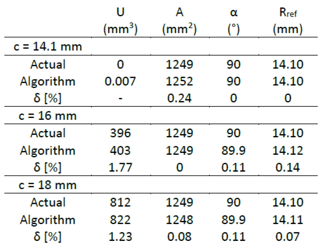
Volumetric wear, measured area, maximal measured angle and reference radius were compared with analytically calculated values for individual data sets. Results of verification of algorithm are summarized in Table 1. There are negligible differences between analytically calculated values compared with the calculation using created algorithm.
Tab. 1. Comparison between analytically calculated results and results calculated by algorithm. 
Results
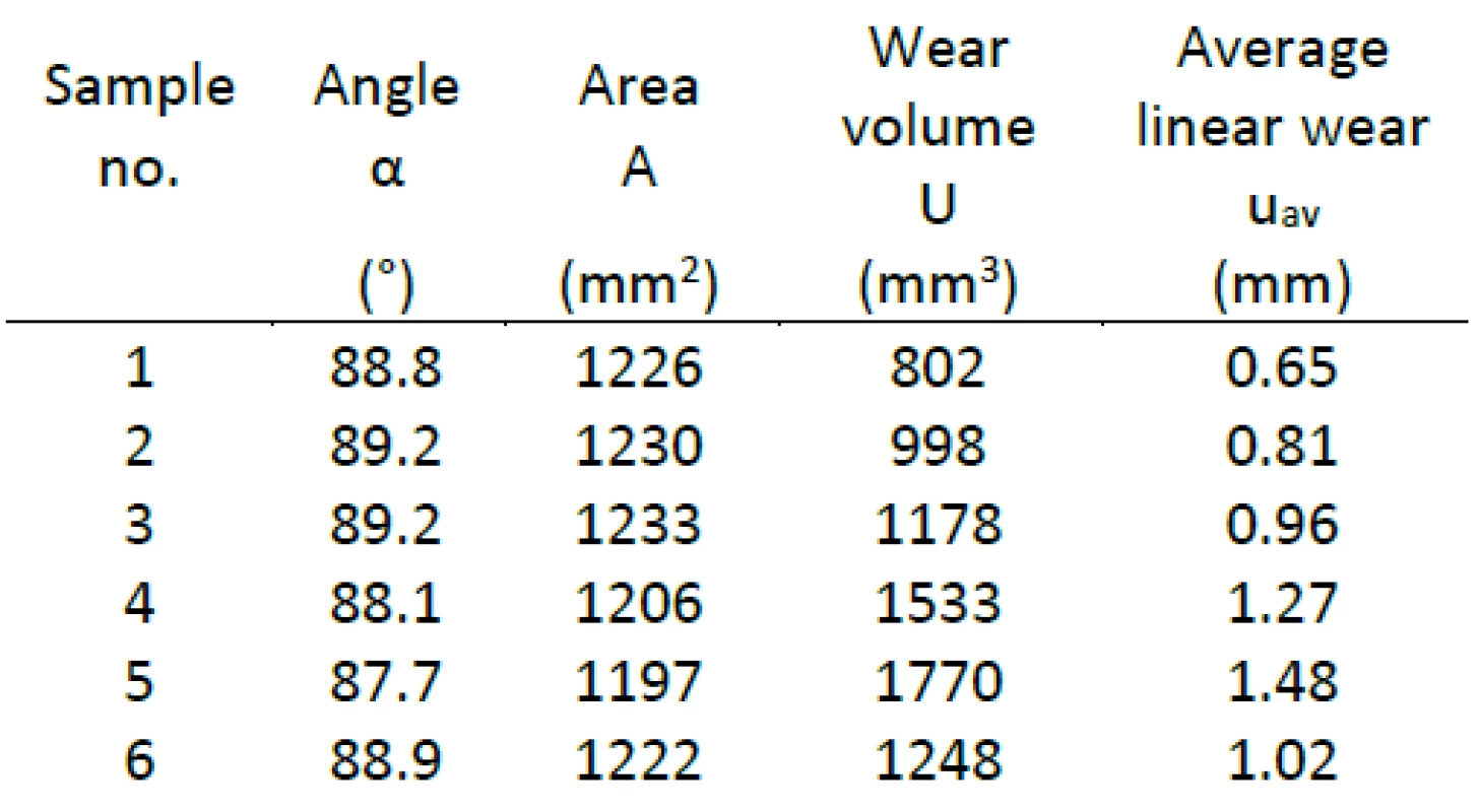
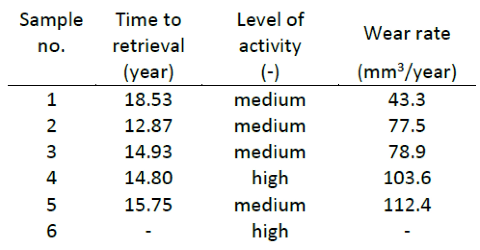
Wear data of measured acetabular cups is summarized in Table 2. Similar to average linear wear, volumetric wear obtained from our measurement was found to be relatively high for all measured samples in comparison with results in literature [3, 6]. This may be related not only to the relatively high time to retrieval, but is associated with the type of patient, implantation technique, and patient activity, all of which may impact the wear rate significantly. Results of wear in comparison with the length of service life and level of patient activity during implantation are summarized in Tab. 3. Level of patient activity was achieved based on the patient history and short questionnaire and is divided into three categories: low, medium and high.
Tab. 2. Results of measured wear. 
Tab. 3. Results of wear in comparison with service life and level of patient activity. 
It should also be noted that the wear volume comprises several modes of surface damage such as pitting, surface deformation, burnishing, abrasion and others [10, 11].
It was important to identify the most and the least damaged areas of acetabular cup for the following analysis. Visualization of linear wear is used for this purpose, which visualizes a scatter of the wear on explanted cups surface in details. Fig. 7 depicts the representative wear map highlighting the wear distribution and pattern on the selected cup determined by the calculation. It can be seen in Fig. 7 some signs of damage caused during explantation. These signs of damage are evident in all measured samples. It should be noted that results of these areas were replaced by interpolation in the relevant areas to calculate the volumetric wear correctly.
Fig. 7: Linear wear distribution on the selected acetabular cup no. 2. 
The color scale bar on the linear wear map showing both positive and negative dimensional changes. The positive scale means actual linear wear (i.e., the measured radii are higher than the radius of reference sphere), and the negative scale may indicate potential deformation and/or unexpected surface damage. It can be seen from the wear map that, as expected, wear is scattered across the surface and the main area of wear is located off the pole, rather close to an edge of the cup and approximately tallies with the component implantation angle.
Conclusion
It was shown in the paper that combination of unique optical CMM technique and Matlab calculations provides an effective tool for the reliable determination of wear of acetabular cups in cases where pre-wear data are not available. The method provides a basis for developing fully spatially localize and characterize wear explanted components. The obtained results can be applied in clinical practice and leading to full wear characterization of explanted components. Another aim is a greater understanding of the tribology and true clinical performance of total replacement joints.
Acknowledgement
Support of the grant NV15-31269A (MZ CR) is gratefully acknowledged.
Ing. Vlastimil Králík, Ph.D.
Department of Mechanics, Biomechanics and Mechatronics
Faculty of Mechanical Engineering
Czech Technical University in Prague
Technická 4, CZ-166 07 Prague 6
E-mail: vlastimil.kralik@fs.cvut.cz
Phone: +420 224 352 533
Zdroje
[1] Bills, P., Blunt, L., Jiang, X.: Development of a technique for accurately determining clinical wear in explanted total hip replacements. Wear. 2007, vol. 263, no. 7–12 , p. 1133–1137.
[2] Kosak, R., Antolic, V., Pavlovcic, V., Kralj-Iglic, V., Milosev, I., Vidmar, G., Iglic, A.: Polyethylene wear in total hip prostheses: the influence of direction of linear wear on volumetric wear determined from radiographic data. Skeletal Radiology. 2003, vol. 32, no. 12, p. 679–686.
[3] Uddin, M. S.: Wear Measurement and Assessment of Explanted Cross-Linked PE Acetabular Cups Using a CMM. Tribology Transactions. 2014, vol. 57, no. 5, p. 767–777.
[4] Lord, J. K., Langton, D. J., Nargol, A. V. F., Joyce, T. J.: Volumetric wear assessment of failed metal-on-metal hip resurfacing prostheses. Wear. 2011, vol. 272, no. 1, p. 79–87.
[5] Gallo, J., Havránek, V., Zapletalová, J., Mandát, D.: Measurement of Acetabular Polyethylene Wear, Using a Universal Measuring Microscope, in Total Hip Replacement. Acta Chirurgiae Orthopaedicae Et Traumatologiae Čechosl. 2006, vol. 73, no. 1, p. 28–33.
[6] Uddin, M. S., Mak, C. Y. E., Callary, S. A.: Evaluating hip implant wear measurements by CMM technique. Wear. 2016, vol. 364, p. 193–200.
[7] Tuke, M., Taylor, A., Roques, A., Maul, C.: 3D linear and volumetric wear measurement on artificial hip joints-Validation of a new methodology. Precision Engineering-Journal of the International Societies for Precision Engineering and Nanotechnology. 2010, vol. 34, no. 4, p. 777–783.
[8] Mervart, J.: Analysis of hip joint cup wear. Prague: CTU 2016. Master thesis, CTU, Faculty of Mechanical Engineering.
[9] ISO 7206-2 : 2011, “Implants for surgery - - Partial and total hip joint prostheses - - Part 2: Articulating surfaces made of metallic, ceramic and plastics materials”.
[10] Trommer, R. M., Maru, M. M., Filho, O. W. L., Nykanen, V. P. S., Gouvea, C. P., Archanjo, B. S., Ferreira, M. E. H., Silva, R. F., Achete, C. A.: Multi-Scale Evaluation of Wear in UHMWPE-Metal Hip Implants Tested in a hip Joint Simulator. Biotribology. 2015, vol. 4, p. 1–11.
[11] Kurtz, S. M.: Chapter 8 - The Clinical Performance of UHMWPE in Knee Replacements. In: Steven M. KURTZ, ed. UHMWPE Biomaterials Handbook (Second Edition). Boston: Academic Press, 2009, pp. 97–116. ISBN 978-0-12-374721-1.
Štítky
Biomedicína
Článek vyšel v časopiseLékař a technika

2017 Číslo 3-
Všechny články tohoto čísla
- DESIGN OF AN EXPERIMENTAL LASER SPECKLE CONTRAST IMAGING SYSTEM AND IMAGE
- RELIABILITY AND SOURCE OF ERRORS IN END-TIDAL GAS CONCENTRATION EVALUATION ALGORITHMS DURING AVALANCHE SNOW AND REBREATHING EXPERIMENTS
- METHODS FOR AUTOMATIC ESTIMATION OF THE NUMBER OF CLUSTERS FOR K-MEANS ALGORITHM USED ON EEG SIGNAL: FEASIBILITY STUDY
- DETERMINATION OF THE GEOMETRICAL AND VISCOELASTIC PROPERTIES OF SCAFFOLDS MADE BY ADdITIVE MANUFACTURING USING BIOPLOTTER
- DEVELOPMENT OF NEW TECHNIQUE FOR ACCURATE WEAR ANALYSIS OF EXPLANTED TOTAL HIP REPLACEMENTS
- Lékař a technika
- Archiv čísel
- Aktuální číslo
- Informace o časopisu
Nejčtenější v tomto čísle- DEVELOPMENT OF NEW TECHNIQUE FOR ACCURATE WEAR ANALYSIS OF EXPLANTED TOTAL HIP REPLACEMENTS
- DESIGN OF AN EXPERIMENTAL LASER SPECKLE CONTRAST IMAGING SYSTEM AND IMAGE
- RELIABILITY AND SOURCE OF ERRORS IN END-TIDAL GAS CONCENTRATION EVALUATION ALGORITHMS DURING AVALANCHE SNOW AND REBREATHING EXPERIMENTS
- DETERMINATION OF THE GEOMETRICAL AND VISCOELASTIC PROPERTIES OF SCAFFOLDS MADE BY ADdITIVE MANUFACTURING USING BIOPLOTTER
Kurzy
Zvyšte si kvalifikaci online z pohodlí domova
Autoři: prof. MUDr. Vladimír Palička, CSc., Dr.h.c., doc. MUDr. Václav Vyskočil, Ph.D., MUDr. Petr Kasalický, CSc., MUDr. Jan Rosa, Ing. Pavel Havlík, Ing. Jan Adam, Hana Hejnová, DiS., Jana Křenková
Autoři: MUDr. Irena Krčmová, CSc.
Autoři: MDDr. Eleonóra Ivančová, PhD., MHA
Autoři: prof. MUDr. Eva Kubala Havrdová, DrSc.
Všechny kurzyPřihlášení#ADS_BOTTOM_SCRIPTS#Zapomenuté hesloZadejte e-mailovou adresu, se kterou jste vytvářel(a) účet, budou Vám na ni zaslány informace k nastavení nového hesla.
- Vzdělávání


